
Without correct 3-wire water pump wiring, motors fail, installations stall, and B2B buyers lose sales seasons. Consequence–Shipment delays, after-sale disputes, and high replacement costs occur. Solution–Follow this clear wiring guide to ensure safe, stable pump setup.
To wire a 3-wire electric water pump, connect the red, yellow, and black motor leads to the matching terminals on the control box marked “Start,” “Run,” and “Common,” then connect the power supply and ground. A 3-wire pump always requires an external control box for proper starting, protection, and direction management.
Keep reading to ensure your water pump wiring is accurate, safe, and ready for long-term operation.
What is a 3-wire pump?
A 3-wire pump is a type of electric water pump, commonly used in deep well and utility pumping systems, that includes three motor leads plus a ground wire. These pumps are designed to work with an external control box, which holds the starting capacitor, relay, and overload protection. Unlike 2-wire pumps that integrate starting components inside the motor, 3-wire pumps separate these functions to improve reliability and allow easier maintenance.
For professional B2B buyers, especially in markets like Russia, Africa, and the Middle East, 3-wire pumps are preferred because they offer smoother starts, better torque, and longer service life under voltage-unstable conditions. The wiring colors vary by brand but generally include red (start), yellow (run), black (common), and green (ground). This configuration makes water pump wiring more precise and reduces the risk of internal overheating.
In wholesale applications or electromechanical supporting projects, 3-wire systems are often chosen because they are easier to diagnose in case of failures. If a capacitor inside a 2-wire pump burns out, the entire motor must be replaced. For a 3-wire pump, the external box can be swapped instantly, which is a major advantage for distributors who want to minimize after-sale costs and keep stock moving.
How does a 3-wire system work?
A 3-wire pump system works by using an external control box to manage the starting and running cycles of the electric water pump. Inside the motor, the red wire powers the start winding, the yellow wire powers the run winding, and the black wire serves as common. When the pump is switched on, the control box sends a strong starting current through the capacitor to the start winding. This gives the pump the torque needed to overcome friction and begin rotating.
Once the pump reaches operating speed, the relay in the control box disconnects the start winding, and the motor continues using only the run winding, drawing stable current and maintaining efficiency. This two-stage operation is why 3-wire systems handle heavy-duty pumping better and maintain smooth performance in deep well installations.
For B2B pump buyers who prioritize reliability and long-term performance—such as wholesalers, project contractors, and pump distributors—this design ensures predictable, stable operation even under difficult conditions. With the control box outside the well, field technicians can easily replace faulty components without pulling the entire unit out of the water. This reduces downtime and prevents lost selling seasons, a key pain point for many overseas pump buyers sourcing from China.
How to wire up a 3-wire plug?
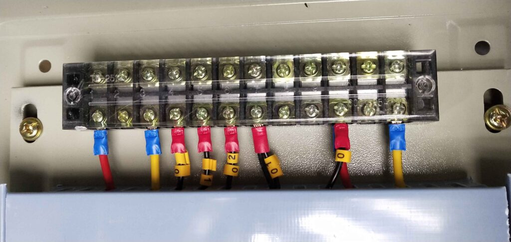
Wiring a 3-wire water pump plug requires accuracy, proper identification of motor leads, and understanding of the control box terminals. First, verify the pump model and check the label inside the control box. The typical terminals include R (Red – Start), Y (Yellow – Run), and B (Black – Common), along with a ground terminal.
Step 1: Turn off all power sources. Safety is essential when working with electric water pumps.
Step 2: Connect the pump’s red, yellow, and black wires to the matching terminals in the control box. If your pump uses alternative color coding, follow the manufacturer diagram or FEILI/CTT’s documentation.
Step 3: Connect the green or bare copper ground wire to the grounding screw to ensure protection against electrical faults.
Step 4: Connect the power supply line (L and N) to the input terminals of the control box. Many installers also add voltage stabilizers when working in regions where power networks are unstable.
Step 5: Check the wiring layout, tighten all screws, and close the control box cover. Loose contacts are one of the most common causes of pump failure in the field.
Step 6: Test the pump by switching it on. The motor should start smoothly without vibration or noise. If it hums but does not start, the start capacitor may be faulty.
For wholesale distributors and engineering clients, correct water pump wiring reduces after-sales complaints and ensures long-term customer trust. This is why CTT’s factory testing includes 100% wiring verification before shipment, helping overseas buyers avoid costly installation mistakes.
Correct 3-wire pump wiring protects your investment and ensures reliable, long-term pumping performance.


